

SolidMechanicsStrain
SolidMechanicsStrain[vars,pars,displ]
yields a solid mechanics total strain with variables vars, parameters pars and displacements displ.
Details
- SolidMechanicsStrain returns the mechanical total strain from a given displacement with dependent variables of displacement
 ,
,  and
and  in units of
  , independent variables
  in
in  and time variable
  in units of
  .
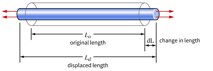
. - Normal strain
 where
where  is the change in length and
  the original length.
 - Strains are unitless.
- SolidMechanicsStrain uses the same variables vars specification as SolidMechanicsPDEComponent.
- SolidMechanicsStrain uses the same parameter pars specification as SolidMechanicsPDEComponent.
- Typically the displacement displ is the result of solving a partial differential equation generated with SolidMechanicsPDEComponent.
- For each dependent variable
 ,
,  and
and  given as dependent variable vector
  in vars, a displacement displ needs to be specified.
 - SolidMechanicsStrain returns a SymmetrizedArray of engineering strains of the form:
- The
 represent the normal strain and
  represent the shear strains.
 - SolidMechanicsStrain returns the total strain
 :
: - The default elastic strain measure
 is based on an infinitesimal strain tensor model
  and assumes small displacements and small rotations.
 - The shear strains used are engineering shear strains related to the tensorial strain by
 .
. - SolidMechanicsStrain returns total strains including inelastic strains
 such as initial or thermal strains.
 - SolidMechanicsStress computes stress from SolidMechanicsStrain.
Examples
open all close allBasic Examples (1)
Scope (6)
Compute the strain from the displacement:
vars = {{u[x, y, z], v[x, y, z], w[x, y, z]}, {x, y, z}};
strain = SolidMechanicsStrain[vars, <||>, vars[[1]]]
Inspect the engineering strain:
MatrixForm[strain]strainTensor = 1 / 2(Grad@@vars + Transpose[Grad@@vars]);
MatrixForm[strainTensor]Verify the relation between the engineering strain and the strain tensor:
strain == {{1, 2, 2}, {2, 1, 2}, {2, 2, 1}} * strainTensorThe default usage of engineering strain in the linear elastic regime can be turned off:
MatrixForm[SolidMechanicsStrain[vars, <|"EngineeringStrain" -> False|>, vars[[1]]]]Stationary Analysis (1)
Compute the deflection of a spoon held fixed at the end and with a force applied at the top. Set up variables and parameters:
vars = {{u[x, y, z], v[x, y, z], w[x, y, z]}, {x, y, z}};
pars = <|"Material" -> ["Silver"]|>;Set up the PDE and the geometry:
spoon = \!\(\*Graphics3DBox[«8»]\);
displacement = NDSolveValue[{SolidMechanicsPDEComponent[vars, pars] == SolidBoundaryLoadValue[x >= 1 / 10, vars, pars, <|"Force" -> {0, 0, Quantity[-100, "Newtons"]}|>],
	SolidFixedCondition[x <= -1 / 10, vars, pars]}, {u, v, w}, {x, y, z}∈spoon];
Compute the strain from the displacement:
strains = SolidMechanicsStrain[vars, pars, displacement]SliceContourPlot3D[strains[[3, 3]], spoon, {x, y, z}∈spoon, ...]Stationary Plane Stress Analysis (2)
Compute the displacement of a rectangular steel plate held fixed at the bottom and with pressures applied at the remaining sides. Set up the region, variables and parameters:
Ω = Rectangle[{0, 0}, {1 / 25, 3 / 100}];
vars = {{u[x, y], v[x, y]}, {x, y}};
pars = <|"SolidMechanicsModelForm" -> "PlaneStress", "YoungModulus" -> 200 * 10 ^ 9, "PoissonRatio" -> 3 / 10, "Thickness" -> 10 ^ -4|>;displacement = NDSolveValue[{SolidMechanicsPDEComponent[vars, pars] == SolidBoundaryLoadValue[x == 1 / 25, vars, pars, <|"Pressure" -> {0, 2 * 10 ^ 8}|>] + SolidBoundaryLoadValue[y == 3 / 100, vars, pars, <|"Pressure" -> {2 * 10 ^ 8, 0}|>] +
SolidBoundaryLoadValue[x == 0, vars, pars, <|"Pressure" -> {0, -2 * 10 ^ 8}|>], SolidFixedCondition[y == 0, vars, pars]}, {u[x, y], v[x, y]}, {x, y}∈Ω]VectorDisplacementPlot[displacement, {x, y}∈Ω, Rule[...]]strain = SolidMechanicsStrain[vars, pars, displacement]Verify that the normal strain in the ![]() direction is about 0:
direction is about 0:
MinMax[strain[[1, 1]][[0]]["ValuesOnGrid"]]Verify that the normal strain in the ![]() direction is about 0:
direction is about 0:
MinMax[strain[[2, 2]][[0]]["ValuesOnGrid"]]MinMax[strain[[1, 2]][[0]]["ValuesOnGrid"]]Compute a plane stress case as an extended model. This allows for the computation of the out-of-plane strain and verifies that the out-of-plane stress is 0. A rectangular steel plate is held fixed at the left and with a forced displacement on the right. Set up the region, variables and parameters. The variables now include all three directions:
Ω = Rectangle[{0, 0}, {40 * 10 ^ -3, 30 * 10 ^ -3}];
vars = {{u[x, y], v[x, y], w[x, y]}, {x, y, z}};
pars = <|"SolidMechanicsModelForm" -> "ExtendedPlaneStress", "YoungModulus" -> 200 * 10 ^ 9, "PoissonRatio" -> 0.3, "Thickness" -> 10 ^ -4|>;
Solve the equations with three semi-dependent variables:
displacement = NDSolveValue[{SolidMechanicsPDEComponent[vars, pars] == {0, 0}, SolidDisplacementCondition[x == 0, vars, pars, <|"Displacement" -> {0, 0}|>], SolidDisplacementCondition[x == 40 * 10 ^ -3, vars, pars, <|"Displacement" -> {-40 / 10 ^ 6, 0}|>]}, {u[x, y], v[x, y], w[x, y]}, {x, y}∈Ω]Note that now there are three output variables in the list of displacements. Visualize the displacement for the main variables:
VectorDisplacementPlot[displacement[[1 ;; 2]], {x, y}∈Ω, Rule[...]]strain = SolidMechanicsStrain[vars, pars, displacement]Note that the strain is a 3×3 array. Visualize the out-of-plane strain:
ContourPlot[strain[[3, 3]], {x, y}∈Ω, PlotRange -> All, PlotLegends -> Automatic]Compute the stress from the strain:
stress = SolidMechanicsStress[vars, pars, strain]Note that the stress is a 3×3 array. Verify the plane stress condition:
stress[[3, 3]]Stationary Plane Strain Analysis (1)
Compute a plane strain case as an extended model. This allows for the computation of the out-of-plane stress and verifies that the out-of-plane strain is 0. Set up the region, variables and parameters. The variables now include all three directions:
Ω = Rectangle[];
pars = <|"SolidMechanicsModelForm" -> "ExtendedPlaneStrain", "YoungModulus" -> 30 * 10 ^ 3, "PoissonRatio" -> 3 / 10, "Thickness" -> 1|>;
vars = {{u[x, y], v[x, y], 0}, {x, y, z}};
Set up the solid mechanics PDE component:
op = SolidMechanicsPDEComponent[vars, pars]pde = {op == {0, 0}, SolidFixedCondition[x == 0, vars, pars], SolidDisplacementCondition[x == 1, vars, pars, <|"Displacement" -> {0.1, None}|>]};displacement = NDSolveValue[pde, {u[x, y], v[x, y], 0}, {x, y}∈Ω]Compute the strains from the displacements:
strain = SolidMechanicsStrain[vars, pars, displacement]Note that the strain is a 3×3 array. Verify the plane strain condition:
strain[[3, 3]]Compute the stress from the strain:
stress = SolidMechanicsStress[vars, pars, strain]Note that the stress is a 3×3 array. Visualize the out-of-plane stress:
ContourPlot[stress[[3, 3]], {x, y}∈Ω, PlotRange -> All, PlotLegends -> Automatic]Stationary Hyperelastic Plane Stress Analysis (1)
Compute the displacement of a rectangular rubber plate held fixed at the left and with force applied at the right-hand side. Set up the region, variables and parameters:
Ω = Rectangle[{0, 0}, {1, 1}];
vars = {{u[x, y], v[x, y]}, {x, y}};
pars = <|"SolidMechanicsMaterialModel" -> "NeoHookeanIsotropic", "LameParameter" -> 10 ^ 6, "ShearModulus" -> 5000, "SolidMechanicsModelForm" -> "PlaneStress", "Thickness" -> 0.01|>;displacement = NDSolveValue[
{SolidMechanicsPDEComponent[vars, pars] == SolidBoundaryLoadValue[x == 1, vars, pars, <|"Force" -> {Quantity[300, "Newtons"], 0}|>], SolidFixedCondition[x == 0, vars, pars]}, {u[x, y], v[x, y]}, {x, y}∈Ω];VectorDisplacementPlot[displacement, {x, y}∈Rectangle[{0, 0}, {1, 1}], ...]Compute the strain from the displacement:
strains = SolidMechanicsStrain[vars, pars, displacement]ContourPlot[strains[[1, 1]], {x, y}∈Ω, PlotRange -> All]Possible Issues (1)
By default, the solid mechanics framework uses engineering strains for the linear elastic regime. This can be switched off.
Set up a helper function with a solid mechanics PDE model:
solve[vars_, pars_] := Module[{displacement}, displacement = NDSolveValue[{SolidMechanicsPDEComponent[vars, pars] == {0, 0, 0}, SolidFixedCondition[x == 0, vars, pars], SolidDisplacementCondition[x == 1, vars, pars, <|"Displacement" -> {0.01, None, None}|>]}, vars[[1]], vars[[-1]]∈Cuboid[]];SolidMechanicsStrain[vars, pars, displacement]
	]
Create variables and parameters:
vars = {{u[x, y, z], v[x, y, z], w[x, y, z]}, {x, y, z}};
pars = <|"Material" -> Entity["Element", "Titanium"]|>;
Solve the solid mechanics model with engineering strains:
str1 = solve[vars, pars];Solve the solid mechanics model with engineering strains off:
str2 = solve[vars, Join[<|"EngineeringStrain" -> False|>, pars]];Verify at a specific point that the shear strains of the engineering formulation relate to the normal strain formulation by a factor of 2:
pos = {x -> 0.01, y -> 0.025, z -> 0.19};
engineeringStrain = Normal[str1] /. pos;
trueStrain = Normal[str2] /. pos;
Chop[({{1, 2, 2}, {2, 1, 2}, {2, 2, 1}} * trueStrain) - engineeringStrain]Text
Wolfram Research (2021), SolidMechanicsStrain, Wolfram Language function, https://reference.wolfram.com/language/ref/SolidMechanicsStrain.html (updated 2025).
CMS
Wolfram Language. 2021. "SolidMechanicsStrain." Wolfram Language & System Documentation Center. Wolfram Research. Last Modified 2025. https://reference.wolfram.com/language/ref/SolidMechanicsStrain.html.
APA
Wolfram Language. (2021). SolidMechanicsStrain. Wolfram Language & System Documentation Center. Retrieved from https://reference.wolfram.com/language/ref/SolidMechanicsStrain.html