

Polygon
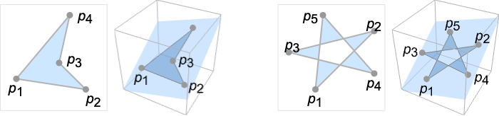
Polygon[{p1,…,pn}]
represents a filled polygon with points pi.
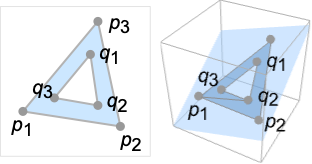
Polygon[{p1,…,pn}{{q1,…,qm},…}]
represents a polygon with holes {q1,…,qm},….
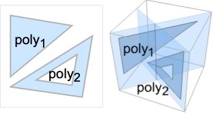
Polygon[{poly1,poly2,…}]
represents a collection of polygons polyi.
Polygon[{p1,…,pn},data]
represents a polygon in which coordinates given as integers i in data are taken to be pi.
Details and Options
- Polygon can be used as a geometric region and a graphics primitive.
- Polygon[{p1,…,pn}] is a plane region, representing all the points inside the closed curve with line segments {p1,p2},…,{pn-1,pn} and {pn,p1}.
- A point is an element of the polygon if a ray from the point in any direction in the plane crosses the boundary line segments an odd number of times.
- Polygon[{p1,…,pn}{{q1,…,qm},…}] specifies a polygon with holes consisting of an outer polygon Polygon[{p1,…,pn}] and one or several inner polygons Polygon[{q1,…,qm}],….
- A point is an element of the polygon if it is in the outer polygon but not in any inner polygon.
- Polygon[{poly1,poly2,…}] is a collection of polygons polyi with or without holes and is treated as a union of polyi for geometric computations.
- Polygon[{p1,…,pn},data] effectively replaces integers i that appear as coordinates in data by the corresponding pi.
-
Polygon[{p1,…,pn},{b1,…,bn}] polygon boundary points {pb1,…,pbk} Polygon[{p1,…,pn},{{o1,…,ok}{{i1,…,il},…}] outer polygon boundary points {po1,…,pok} and inner polygon boundary {pi1,…,pil} etc. Polygon[{p1,…,pn},{{b1,…,bn},{o1,…,ok}{{i1,…,il},…},…}] a collection of several polygons - As a geometric region, the points pi can have any embedding dimension, but must all lie in a plane and have the same embedding dimension.
- In a graphic, the points pi can be Scaled, Offset, ImageScaled and Dynamic expressions.
- Graphics rendering is affected by directives such as FaceForm, EdgeForm, Texture, Specularity, Opacity and color.
- FaceForm[front,back] can be used to specify different styles for the front and back of polygons in 3D. The front is defined by the right-hand rule and the direction of the first three points.
- The following options and settings can be used in graphics:
-
VertexColors Automatic vertex colors to be interpolated VertexNormals Automatic effective vertex normals for shading VertexTextureCoordinates None coordinates for textures - Polygon can be used with symbolic points in GeometricScene.
Examples
open all close allBasic Examples (2)
pol = Polygon[{{1, 0}, {0, Sqrt[3]}, {-1, 0}}]Graphics[pol]Area[pol]Differently styled 3D polygons:
pol = Polygon[{{1, 0, 0}, {1, 1, 1}, {0, 0, 1}}];{Graphics3D[{Pink, pol}], Graphics3D[{EdgeForm[Thick], Pink, pol}], Graphics3D[{EdgeForm[Dashed], Pink, pol}]}Scope (22)
Graphics (12)
Specification (3)
p2 = {{0, 0}, {1, 0}, {0, 1}};Graphics[Polygon[{p2, p2 + 1}]]p3 = {{1, 0, 0}, {1, 1, 1}, {0, 0, 1}};Graphics3D[Polygon[{p3, p3 + 1}]]Polygons with multiple vertices:
Graphics[Polygon[Table[{Cos[2π k / 6], Sin[2π k / 6]}, {k, 0, 5}]]]Graphics3D[Polygon[Table[{Cos[2π k / 6], Sin[2π k / 6], 0}, {k, 0, 5}]]]Graphics[Polygon[{{0, 0}, {2, 0}, {1, Sqrt[3]}} -> {{{(1/2), (1/2 Sqrt[3])}, {(3/2), (1/2 Sqrt[3])}, {1, (2/Sqrt[3])}}}]]Graphics3D[Polygon[{{0, 0, 0}, {2, 0, 0}, {1, Sqrt[3], 0}} -> {{{(1/2), (1/2 Sqrt[3]), 0}, {(3/2), (1/2 Sqrt[3]), 0}, {1, (2/Sqrt[3]), 0}}}]]Styling (6)
Color directives specify the face colors of polygons:
Table[Graphics[{c, Polygon[{{1, 0}, {0, Sqrt[3]}, {-1, 0}}]}], {c, {Red, Green, Blue, Yellow}}]Table[Graphics3D[{c, Polygon[{{1, 0, 0}, {1, 1, 1}, {0, 0, 1}}]}], {c, {Red, Green, Blue, Yellow}}]Texture can be used to specify a texture to be used on the faces of polygons:
{Graphics[{Texture[ExampleData[{"TestImage", "JellyBeans2"}]], Polygon[{{1, 0}, {0, Sqrt[3]}, {-1, 0}}, VertexTextureCoordinates -> {{1, 0}, {0.5, 1}, {0, 0}}]}], Graphics3D[{Texture[ExampleData[{"TestImage", "JellyBeans2"}]], Polygon[{{0, 0, 0}, {1, 1, 0}, {0, 1, 1}}, VertexTextureCoordinates -> {{0, 0}, {1, 0}, {0.5, 1}}]}, Lighting -> "Neutral"]}Texture can work together with different Opacity:
Table[Graphics[{Opacity[o], Texture[ExampleData[{"TestImage", "House"}]], Polygon[{{1, 0}, {0, Sqrt[3]}, {-1, 0}}, VertexTextureCoordinates -> {{1, 0}, {0.5, 1}, {0, 0}}]}], {o, {0.25, 0.5, 0.75, 1}}]Texture can work together with different Lighting:
Table[Graphics3D[{Texture[ExampleData[{"TestImage", "Sailboat"}]], Polygon[{{0, 0, 0}, {1, 1, 0}, {0, 1, 1}}, VertexTextureCoordinates -> {{0, 0}, {1, 0}, {0.5, 1}}]}, Lighting -> {{"Directional", c, {4, -4, 4}}}], {c, {Red, Green, Yellow, White}}]FaceForm and EdgeForm can be used to specify the styles of the interiors and boundaries:
Graphics[{FaceForm[Pink], EdgeForm[Directive[Dashed, Thick, Blue]], Polygon[{{0, 0}, {0, 1}, {1, 1}, {1, 0}}]}]Graphics3D[{FaceForm[Pink], EdgeForm[Directive[Dashed, Thick, Blue]], Polygon[{{0, 0, 0}, {1, 1, 0}, {1, 1, 1}, {0, 0, 1}}]}]In 3D, different properties can be specified for the front and back of faces using FaceForm:
p = {FaceForm[Yellow, Blue], Polygon[{{1, 0, 0}, {0, Sqrt[3], 0}, {-1, 0, 0}}]};{Graphics3D[p, ViewPoint -> Top], Graphics3D[p, ViewPoint -> Bottom]}Use FaceForm to set front and back textures differently in 3D:
vtc = {{0, 0}, {1, 0}, {1, 1}, {0, 1}};
coords = {{{0, 0, 0}, {0, 1, 0}, {1, 1, 0}, {1, 0, 0}}, {{0, 0, 0}, {1, 0, 0}, {1, 0, 1}, {0, 0, 1}}, {{1, 0, 0}, {1, 1, 0}, {1, 1, 1}, {1, 0, 1}}, {{1, 1, 0}, {0, 1, 0}, {0, 1, 1}, {1, 1, 1}}, {{0, 1, 0}, {0, 0, 0}, {0, 0, 1}, {0, 1, 1}}};Graphics3D[{FaceForm[Texture[[image]], Texture[[image]]], Polygon[coords, VertexTextureCoordinates -> Table[vtc, {6}]]}, Lighting -> "Neutral"]Colors can be specified at vertices using VertexColors:
Graphics[Polygon[{{1, 0}, {0, Sqrt[3]}, {-1, 0}}, VertexColors -> {Red, Green, Blue}]]Graphics3D[Polygon[{{1, 0, 0}, {1, 1, 1}, {0, 0, 1}}, VertexColors -> {Red, Green, Blue}]]Normals can be specified at vertices using VertexNormals for 3D polygons:
n = {1, -1, 1};Graphics3D[{Yellow, Polygon[{{1, 0, 0}, {1, 1, 1}, {0, 0, 1}}, VertexNormals -> {-n, n, n}]}]Coordinates (3)
Use Scaled coordinates:
Graphics[Polygon[{Scaled[{0, 0}], Scaled[{.5, 1}], Scaled[{1, 0}]}], Frame -> True]Graphics3D[Polygon[{Scaled[{0, 0, .2}], Scaled[{.5, 1, .8}], Scaled[{1, 0, .2}]}], Axes -> True]Use ImageScaled coordinates in 2D:
Graphics[Polygon[{ImageScaled[{0, 0}], ImageScaled[{.5, 1}], ImageScaled[{1, 0}]}], Frame -> True]Use Offset coordinates in 2D:
Graphics[Polygon[{Offset[{10, 10}, {0, 0}], Offset[{0, -20}, {.5, 1}], Offset[{-10, 10}, {1, 0}]}], Frame -> True]Regions (10)
RegionEmbeddingDimension[Polygon[{{1, 0, 0}, {1, 1, 1}, {0, 0, 1}}]]RegionDimension[Polygon[{{1, 0, 0}, {1, 1, 1}, {0, 0, 1}}]]ℛ = Polygon[{{1, 0, 0}, {1, 1, 1}, {0, 0, 1}}];{RegionMember[ℛ, {2 / 3, 1 / 3, 2 / 3}], RegionMember[ℛ, {0, 0, 0}]}Get conditions for point membership:
RegionMember[ℛ, {x, y, z}]ℛ = Polygon[{{1, 0}, {1, 1}, {0, 0}}];{Area[ℛ], RegionMeasure[ℛ]}c = RegionCentroid[ℛ]Graphics[{{Pink, ℛ}, {Black, Point[c]}}]ℛ = Polygon[{{-2, 0}, {-1, 3 / 2}, {1, 3 / 2}, {2, 0}, {1, -3 / 2}, {-1, -3 / 2}}];{RegionDistance[ℛ, {3, 4}], RegionDistance[ℛ, {1, 1}]}{Plot3D[Evaluate@RegionDistance[ℛ, {x, y}], {x, -3, 3}, {y, -3, 3}, MeshFunctions -> {#3&}, Mesh -> 5], ContourPlot[Evaluate@RegionDistance[ℛ, {x, y}], {x, -4, 4}, {y, -4, 4}, Contours -> {{0.5, Red}, {1, Green}, {1.5, Blue}}]}ℛ = Polygon[{{-2, 0}, {-1, 3 / 2}, {1, 3 / 2}, {2, 0}, {1, -3 / 2}, {-1, -3 / 2}}];{SignedRegionDistance[ℛ, {3, 4}], SignedRegionDistance[ℛ, {1, 1}]}Plot3D[SignedRegionDistance[ℛ, {x, y}], {x, -3, 3}, {y, -3, 3}, MeshFunctions -> {#3&}, Mesh -> {{0}}, MeshShading -> {Red, Green}]ℛ = Polygon[{{-2, 0}, {-1, 3 / 2}, {1, 3 / 2}, {2, 0}, {1, -3 / 2}, {-1, -3 / 2}}];RegionNearest[ℛ, {3, 4}]pts = Table[4{Cos[k 2 π / 25], Sin[k 2π / 25]}, {k, 0., 24}];
nst = RegionNearest[ℛ, #]& /@ pts;Legended[Graphics[{{Gray, ℛ}, {Thin, Gray, Line[Transpose[{pts, nst}]]}, {Red, Point[pts]}, {Blue, Point[nst]}}], PointLegend[{Red, Blue}, {"start", "nearest"}]]ℛ = Polygon[{{-2, 0}, {-1, 3 / 2}, {1, 3 / 2}, {2, 0}, {1, -3 / 2}, {-1, -3 / 2}}];BoundedRegionQ[ℛ]rr = RegionBounds[ℛ]Graphics[{ℛ, {EdgeForm[{Dashed, Red}], Opacity[0.2, Yellow], Cuboid@@Transpose[rr]}}]Integrate over a polygon:
ℛ = Polygon[{{-2, 0}, {-1, 3 / 2}, {1, 3 / 2}, {2, 0}, {1, -3 / 2}, {-1, -3 / 2}}];Integrate[x ^ 2 + y ^ 2, {x, y}∈ℛ]ℛ = Polygon[{{-2, 0}, {-1, 3 / 2}, {1, 3 / 2}, {2, 0}, {1, -3 / 2}, {-1, -3 / 2}}];Minimize[{x y - x, {x, y}∈ℛ}, {x, y}]ℛ = Polygon[{{-2, 0}, {-1, 3 / 2}, {1, 3 / 2}, {2, 0}, {1, -3 / 2}, {-1, -3 / 2}}];Solve[x^2 + y^2 == 4 && {x, y}∈ℛ, {x, y}]Graphics[{{LightBlue, EdgeForm[Gray], ℛ}, {Green, Circle[{0, 0}, 2]}, {Red, PointSize[Medium], Point[{x, y} /. %]}}]Options (7)
VertexColors (2)
VertexNormals (1)
Compute normal vectors using the cross product of edge vectors:
{p1, p2, p3} = {{1, 0, 0}, {1, 1, 1}, {0, 0, 1}};n = Cross[p2 - p1, p3 - p1]A triangle with normals pointing in the direction {1,-1,1}:
Graphics3D[{Yellow, Polygon[{p1, p2, p3}, VertexNormals -> {n, n, n}]}]Using different normals will affect shading:
Graphics3D[{Yellow, Polygon[{p1, p2, p3}, VertexNormals -> {-n, n, n}]}]VertexTextureCoordinates (4)
Graphics[{Texture[ExampleData[{"TestImage", "Flower"}]], Polygon[{{1, 0}, {0, Sqrt[3]}, {-1, 0}}, VertexTextureCoordinates -> {{1, 0}, {0.5, 1}, {0, 0}}]}]Texture mapping with 2D polygons:
Graphics[{Texture[ExampleData[{"TestImage", "Airplane2"}]], Polygon[{{1, 1}, {3, 1}, {3, 3}, {1, 3}}, VertexTextureCoordinates -> {{0, 0}, {1, 0}, {1, 1}, {0, 1}}]}]Texture mapping with 3D polygons:
Graphics3D[{Texture[ExampleData[{"TestImage", "Airplane2"}]], Polygon[{{-1, -1, 0}, {1, -1, 0}, {1, 1, 0}, {-1, 1, 0}}, VertexTextureCoordinates -> {{0, 0}, {1, 0}, {1, 1}, {0, 1}}]}, Lighting -> "Neutral"]Repeat a texture by using non-unified texture coordinate values:
{Graphics[{Texture[ExampleData[{"TestImage", "Mandrill"}]], Polygon[{{1, 1}, {3, 1}, {3, 3}, {1, 3}}, VertexTextureCoordinates -> {{0, 0}, {2, 0}, {2, 2}, {0, 2}}]}], Graphics3D[{Texture[ExampleData[{"TestImage", "Mandrill"}]], Polygon[{{-1, -1, 0}, {1, -1, 0}, {1, 1, 0}, {-1, 1, 0}}, VertexTextureCoordinates -> {{0, 0}, {2, 0}, {2, 2}, {0, 2}}]}, Lighting -> "Neutral"]}Texture mapping is preceded by VertexColors:
Graphics3D[{Texture[[image]], Polygon[{{-1, -1, -1}, {1, -1, -1}, {1, 1, -1}, {-1, 1, -1}}, VertexTextureCoordinates -> {{0, 0}, {1, 0}, {1, 1}, {0, 1}},
	VertexColors -> {Red, Green, Blue, Purple}]}, Lighting -> "Neutral"]
Applications (3)
Define a polygon with ![]() vertices:
vertices:
ngon[p_, q_] := Polygon[Table[{Cos[2Pi k q / p], Sin[2Pi k q / p]}, {k, p}]]Row[Table[Graphics[{EdgeForm[Red], LightRed, ngon[n, 1]}, ImageSize -> 70], {n, 3, 14}]]Row[Reap[Table[Table[If[CoprimeQ[p, q], Sow[Graphics[{EdgeForm[Green], LightGreen, ngon[p, q]}, ImageSize -> 70]]], {q, 2, p / 2}], {p, 5, 12}]][[2, 1]]]h[x_, y_] := Polygon[Table[{Cos[2Pi k / 6] + x, Sin[2Pi k / 6] + y}, {k, 6}]]Graphics[{EdgeForm[Opacity[.7]], StandardBlue, Table[h[3i + 3((-1) ^ j + 1) / 4, Sqrt[3] / 2j], {i, 5}, {j, 10}]}]Get face polygons from PolyhedronData:
p = N[PolyhedronData["TruncatedIcosahedron", "Faces", "Polygon"]];Shrink each face with respect to the centroid:
shrink[t_, Polygon[x_List, opts___]] := Module[{c = Plus@@x / Length[x]}, Polygon[Map[(c + (1 - t)(# - c))&, x], opts]]Animate[Graphics3D[{FaceForm[Yellow, Green], p /. y_Polygon :> shrink[s, y]}, PlotRange -> 2.5], {s, 0, .8}, SaveDefinitions -> True, AnimationRunning -> False, AnimationDirection -> ForwardBackward, DefaultDuration -> 1]Properties & Relations (4)
GraphicsComplex offers an efficient way to generate a polygon with many shared vertices:
v = {{0, 0, 0}, {2, 0, 0}, {2, 2, 0}, {0, 2, 0}, {1, 1, 2}};i = {{1, 2, 5}, {2, 3, 5}, {3, 4, 5}, {4, 1, 5}};{Graphics3D[{Opacity[.7], GraphicsComplex[v, Polygon[i]]}], Graphics3D[{GraphicsComplex[v, Line[i]]}]}Applying Normal to the graphics complex produces ordinary polygons:
Normal[GraphicsComplex[v, Polygon[i]]]Polygon is a generalization of Triangle:
Subscript[ℛ, 1] = Polygon[{{0, 0}, {1, 0}, {1, 1}}];
Subscript[ℛ, 2] = Triangle[{{0, 0}, {1, 0}, {1, 1}}];RegionEqual[Subscript[ℛ, 1], Subscript[ℛ, 2]]Polygon is a generalization of Rectangle:
Subscript[ℛ, 1] = Polygon[{{0, 0}, {1, 0}, {1, 1}, {0, 1}}];
Subscript[ℛ, 2] = Rectangle[{0, 0}, {1, 1}];RegionEqual[Subscript[ℛ, 1], Subscript[ℛ, 2]]A Simplex with three vertices is a special case of Polygon:
Subscript[ℛ, 1] = Polygon[{{0, 0}, {1, 0}, {1, 1}}];
Subscript[ℛ, 2] = Simplex[{{0, 0}, {1, 0}, {1, 1}}];RegionEqual[Subscript[ℛ, 1], Subscript[ℛ, 2]]In any number of dimensions starting from 2:
Subscript[ℛ, 1] = Polygon[{{0, 0, 0}, {1, 0, 0}, {1, 1, 0}}];
Subscript[ℛ, 2] = Simplex[{{0, 0, 0}, {1, 0, 0}, {1, 1, 0}}];RegionEqual[Subscript[ℛ, 1], Subscript[ℛ, 2]]Possible Issues (3)
In 3D, if the vertices are not in a plane, the polygon triangulation can be unpredictable:
Graphics3D[Polygon[{{0, 0, 0}, {1, 1, 0}, {0, 1, 0}, {0, 0, 1}}]]Graphics3D[Polygon[RandomReal[1, {10, 3}]]]Degenerate polygons are not valid geometric regions:
Polygon[{{0, 0, 0}, {1, 1, 0}, {0, 1, 0}, {0, 0, 1}}]RegionQ[%]Seams can sometimes appear between individual polygons as a result of antialiasing:
Graphics[{Gray, Table[Polygon[{{x, 0}, {x + 1, 0}, {x + 1, 1}, {x, 1}}], {x, 0, 2}]}]Using a single polygon object avoids any seams:
Graphics[{Gray, Polygon[Table[{{x, 0}, {x + 1, 0}, {x + 1, 1}, {x, 1}}, {x, 0, 2}]]}]Neat Examples (3)
Graphics[Table[{EdgeForm[Black], Hue[RandomReal[]], Polygon[RandomReal[1, {3, 2}]]}, {30}]]Graphics3D[Table[{EdgeForm[Black], Opacity[.7], Hue[RandomReal[]], Polygon[RandomReal[1, {3, 3}]]}, {30}], Lighting -> "Neutral"]With[{d = 2Pi / 12}, Graphics[Table[{EdgeForm[Opacity[.6]], Hue[(-11 + q + 10 r) / 72], Polygon[{(8 - r){Cos[d(q - 1)], Sin[d(q - 1)]}, (8 - r){Cos[d(q + 1)], Sin[d(q + 1)]}, (10 - r){Cos[d q], Sin[d q]}}]}, {r, 6}, {q, 12}]]]Animate[Graphics[Rotate[Polygon[Table[{Cos[t], Sin[t]}, {t, 0, 4Pi, 4Pi / 5}]], θ, {0, 0}], PlotRange -> 1.2], {θ, 0, 2π}, AnimationRunning -> False]Text
Wolfram Research (1988), Polygon, Wolfram Language function, https://reference.wolfram.com/language/ref/Polygon.html (updated 2019).
CMS
Wolfram Language. 1988. "Polygon." Wolfram Language & System Documentation Center. Wolfram Research. Last Modified 2019. https://reference.wolfram.com/language/ref/Polygon.html.
APA
Wolfram Language. (1988). Polygon. Wolfram Language & System Documentation Center. Retrieved from https://reference.wolfram.com/language/ref/Polygon.html