


AnatomyPlot3D
AnatomyPlot3D[primitives,options]
represents a three-dimensional graphical image that works with anatomical entities as well as standard 3D graphics primitives and directives.
Details and Options
- Using AnatomyPlot3D requires internet connectivity.
- AnatomyPlot3D allows standalone anatomical entities to represent annotated 3D primitives, substituting the "Graphics3D" property of the entity.
- Entities that appear inside of primitives act as coordinate specifiers, substituting the "RegionCentroid" of the entity.
- AnatomyPlot3D is displayed in StandardForm as a graphical image.
- PlotRange can be specified using anatomical entities, substituting the "RegionBounds" of the entity.
- Coordinate values of the human and animal anatomical entities correspond to an average adult human male and average adult animal, respectively, measured in millimeters.
- AnatomyPlot3D uses the same directives as Graphics3D, with the following addition:
-
AnatomyStyling[directives] anatomical entities are to be drawn using the specified graphics directives - AnatomyPlot3D has the same options as Graphics3D, with the following additions and changes: [List of all options]
-
Boxed False whether to draw the bounding box Lighting "Neutral" simulated light sources to use PlotTheme $PlotTheme overall theme for the plot AnatomySkinStyle None style to be applied to automatically included nearest skin subparts ViewPoint {0,-1.9,0} viewing position - Anatomy base themes include:
-

"Business" a bold, modern design 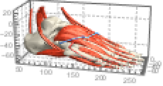
"Detailed" identify size using labeled axes and grid lines 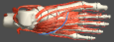
"Marketing" elegant design suitable for marketing needs 
"Minimal" flat shading with minimal detail 
"Monochrome" single-color design 
"Scientific" individually colored parts identified by tooltip 
"Web" bright shading and color suitable for web 
"Classic" historical dark coloring - Anatomy feature themes include:
-
"Transparent" gray transparency 
{"Transparent",color} color transparency 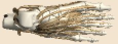
"Vintage" sepia-toned illustrative design 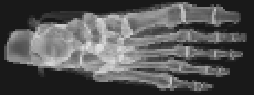
"XRay" gray transparency with bone emphasis - Anatomy color feature themes include individually colored parts identified by tooltip:
-
"BoldColor" 12 bold colors 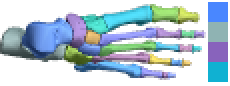
"CoolColor" 8 cool colors 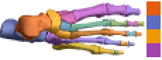
"DarkColor" 8 dark colors 
"NeonColor" 8 neon colors 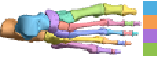
"PastelColor" 8 pastel colors 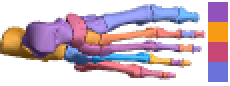
"RoyalColor" 8 royal colors 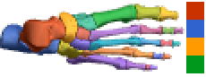
"VibrantColor" 10 vibrant colors 
"WarmColor" 8 warm colors
List of all options
Examples
open all close allBasic Examples (5)
AnatomyPlot3D[Entity["AnatomicalStructure", "LeftFemur"]]AnatomyPlot3D[Entity["AnimalAnatomicalStructure", "LeftFemur::CanisLupusFamiliaris::4t62p"]]AnatomyPlot3D[{Entity["AnatomicalStructure", "RightHand"]}]AnatomyPlot3D[{Entity["AnimalAnatomicalStructure", "LeftForefoot::CanisLupusFamiliaris::4t62p"]}]Coloring and styling of entities:
AnatomyPlot3D[{Entity["AnatomicalStructure", "LeftClavicle"], StandardRed, Entity["AnatomicalStructure", "LeftScapula"]}]Use a theme for stylized effects:
AnatomyPlot3D[{Entity["AnatomicalStructure", "RightHand"]}, PlotTheme -> "Business"]Use entities in arbitrary graphics primitives:
AnatomyPlot3D[{Entity["AnatomicalStructure", "LeftHand"], AbsoluteThickness[2], StandardBlue, Arrow[{Entity["AnatomicalStructure", "DistalPhalanxOfLeftThumb"], Entity["AnatomicalStructure", "DistalPhalanxOfLeftIndexFinger"]}]}]Scope (11)
Coloring and Styling (3)
You can color all entities one style:
AnatomyPlot3D[{StandardBlue, Entity["AnatomicalStructure", "LeftArm"]}]The following example shows that “intermediate” structures like biceps brachii can be handled, even though they are made of smaller atomic components:
AnatomyPlot3D[{AnatomyStyling[<|Entity["AnatomicalStructure", "BicepsBrachii"] -> StandardGreen|>], Entity["AnatomicalStructure", "LeftArm"]}]The following example shows that you can also style the lower-level atomic structures separately:
AnatomyPlot3D[{AnatomyStyling[<|Entity["AnatomicalStructure", "LongHeadOfLeftBicepsBrachii"] -> StandardGreen, Entity["AnatomicalStructure", "ShortHeadOfLeftBicepsBrachii"] -> StandardBlue|>], Entity["AnatomicalStructure", "LeftArm"]}]The following example shows that you can color all objects one color, with the exception of muscles (or any other entity), which are a different color:
AnatomyPlot3D[{AnatomyStyling[<|_ -> StandardRed, Entity["AnatomicalStructure", "Muscle"] -> StandardBlue|>], Entity["AnatomicalStructure", "LeftArm"]}]With no arguments, AnatomyStyling behaves like FaceForm[]:
AnatomyPlot3D[{AnatomyStyling[], EdgeForm[StandardBlue], Entity["AnatomicalStructure", "SeventhCervicalVertebra"]}]AnatomyStyling["Natural"] restores styles to their original state, ignoring earlier directives:
AnatomyPlot3D[{StandardRed, Entity["AnatomicalStructure", "SeventhCervicalVertebra"], AnatomyStyling["Natural"], Entity["AnatomicalStructure", "FirstThoracicVertebra"]}]Primitives (6)
Drawing a line involving entities:
AnatomyPlot3D[{Entity["AnatomicalStructure", "LeftHand"], Entity["AnatomicalStructure", "RightHand"], StandardRed, Line[{Entity["AnatomicalStructure", "LeftHand"], Entity["AnatomicalStructure", "RightHand"]}]}]Drawing an arrow involving entities:
AnatomyPlot3D[{Entity["AnatomicalStructure", "SkeletonOfRightHand"], StandardRed, Arrow[{{-175, -130, 758}, Entity["AnatomicalStructure", "RightFifthMetacarpalBone"]}, 5], Text["5th metacarpal", {-175, -130, 758}, {0, -1}]}]Drawing a cuboid involving entities:
AnatomyPlot3D[{Entity["AnatomicalStructure", "HipBone"], Entity["AnatomicalStructure", "Scapula"], Opacity[.5, StandardRed], Cuboid[Entity["AnatomicalStructure", "LeftHipBone"], Entity["AnatomicalStructure", "RightScapula"]]}]Drawing a sphere involving entities:
AnatomyPlot3D[{Entity["AnatomicalStructure", "SkeletonOfLeftUpperLimb"], Opacity[.5], Sphere[Entity["AnatomicalStructure", "LeftElbow"], 50]}]Drawing a cylinder involving entities:
AnatomyPlot3D[{Entity["AnatomicalStructure", "LeftHumerus"], Entity["AnatomicalStructure", "LeftHand"], Opacity[.3], Cylinder[{Entity["AnatomicalStructure", "LeftElbow"], Entity["AnatomicalStructure", "LeftWrist"]}, 20]}]Drawing a tube involving entities:
AnatomyPlot3D[{Entity["AnatomicalStructure", "LeftClavicle"], Entity["AnatomicalStructure", "LeftScapula"], Entity["AnatomicalStructure", "LeftHand"], StandardRed, Tube[{Entity["AnatomicalStructure", "LeftShoulder"], Entity["AnatomicalStructure", "LeftElbow"], Entity["AnatomicalStructure", "LeftWrist"]}, 10]}]Labeling Subparts (1)
Cutting Layers (1)
Apply a clipping plane to an anatomical structure:
AnatomyPlot3D[{Entity["AnatomicalStructure", "Aorta"], ClipPlanes -> {InfinitePlane[{{-3, -123, 1226}, {17, -143, 1226}, {-3, -143, 1206}}]}, Entity["AnatomicalStructure", "Heart"]}, PlotRange -> Entity["AnatomicalStructure", "Heart"]]Apply multiple clipping planes to an anatomical structure:
AnatomyPlot3D[{Entity["AnatomicalStructure", "LeftHand"], ClipPlanesStyle -> {Directive[Opacity[.3], StandardRed], Directive[Opacity[.3], StandardBlue]}, ClipPlanes -> {InfinitePlane[{{273 - 20, -146, 725}, {273 - 20, -146 - 20, 725}, {273, -146 - 20, 725}}], InfinitePlane[{{273 + 20, -146 - 20, 735}, {273 + 20, -146, 735 - 20}, {273, -146 - 20, 735 - 20}}]}, Entity["AnatomicalStructure", "SkinOfLeftHand"]}, Boxed -> True, Axes -> True]Options (29)
AnatomySkinStyle (3)
Automatically include the nearest skin subpart for anatomical structure entities:
AnatomyPlot3D[{Entity["AnatomicalStructure", "LeftFemur"], Entity["AnatomicalStructure", "RightFemur"]}, AnatomySkinStyle -> Automatic]The default styling can be overridden:
AnatomyPlot3D[{StandardRed, Entity["AnatomicalStructure", "PituitaryGland"]}, AnatomySkinStyle -> Directive[StandardBlue, Opacity[.3]], ViewPoint -> Left]The default behavior is to not include any skin subparts:
AnatomyPlot3D[{Entity["AnatomicalStructure", "LeftFemur"]}, AnatomySkinStyle -> None]Axes (3)
By default, Axes is not drawn for AnatomyPlot3D:
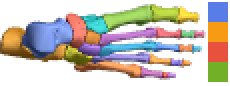
AnatomyPlot3D[{Entity["AnimalAnatomicalStructure", "LeftForefoot::CanisLupusFamiliaris::4t62p"]}]AnatomyPlot3D[{Entity["AnimalAnatomicalStructure", "LeftForefoot::CanisLupusFamiliaris::4t62p"]}, Axes -> True]Turn each axis on individually:
{AnatomyPlot3D[{Entity["AnimalAnatomicalStructure", "LeftForefoot::CanisLupusFamiliaris::4t62p"]}, PlotLabel -> "X axis", Axes -> {True, False, False}], AnatomyPlot3D[{Entity["AnimalAnatomicalStructure", "LeftForefoot::CanisLupusFamiliaris::4t62p"]}, PlotLabel -> "Y axis", Axes -> {False, True, False}], AnatomyPlot3D[{Entity["AnimalAnatomicalStructure", "LeftForefoot::CanisLupusFamiliaris::4t62p"]}, PlotLabel -> "Z axis", Axes -> {False, False, True}]}AxesLabel (3)
No axis labels are drawn by default:
AnatomyPlot3D[{Entity["AnimalAnatomicalStructure", "LeftForefoot::CanisLupusFamiliaris::4t62p"]}, Axes -> True]AnatomyPlot3D[{Entity["AnimalAnatomicalStructure", "LeftForefoot::CanisLupusFamiliaris::4t62p"]}, Axes -> True, AxesLabel -> z]AnatomyPlot3D[{Entity["AnimalAnatomicalStructure", "LeftForefoot::CanisLupusFamiliaris::4t62p"]}, Axes -> True, AxesLabel -> {x, y, z}]AxesOrigin (2)
The position of the axes is determined automatically:
AnatomyPlot3D[{Entity["AnimalAnatomicalStructure", "LeftForefoot::CanisLupusFamiliaris::4t62p"]}, Axes -> True]Specify an explicit origin for the axes:
AnatomyPlot3D[{Entity["AnimalAnatomicalStructure", "LeftForefoot::CanisLupusFamiliaris::4t62p"]}, Axes -> True, AxesOrigin -> {0, 0, -100}]AxesStyle (4)
Change the style for the axes:
AnatomyPlot3D[Entity["AnatomicalStructure", "LeftHand"], Axes ->
	True, AxesStyle -> StandardRed]
Specify the style of each axis:
AnatomyPlot3D[Entity["AnatomicalStructure", "LeftHand"], Axes ->
	True, AxesStyle -> {Directive[Thick, StandardRed], Directive[Thick, StandardBlue], Directive[Thick, StandardGreen]}]
Use different styles for the ticks and the axes:
AnatomyPlot3D[Entity["AnatomicalStructure", "LeftHand"], Axes ->
	True, AxesStyle -> StandardBlue, TicksStyle -> StandardRed]
Use different styles for the labels and the axes:
AnatomyPlot3D[Entity["AnatomicalStructure", "LeftHand"], Axes ->
	True, AxesStyle -> StandardPurple, LabelStyle -> StandardRed]
Method (2)
Tooltips are enabled by default, but they can be disabled by using "Tooltips":
AnatomyPlot3D[Entity["AnatomicalStructure", "LeftIndexFinger"], Method -> {"Tooltips" -> False}]Tooltips are disabled by default for some PlotTheme settings, but they can be enabled using "Tooltips":
AnatomyPlot3D[Entity["AnatomicalStructure", "LeftIndexFinger"], PlotTheme -> "Minimal", Method -> {"Tooltips" -> True}]By default, some structures may have white space around them:
AnatomyPlot3D[Entity["AnatomicalStructure", "LeftFoot"]]White space around these 3D structures can be minimized using "ShrinkWrap":
AnatomyPlot3D[Entity["AnatomicalStructure", "LeftFoot"], Method -> {"ShrinkWrap" -> True}]PlotRange (1)
Restrict the PlotRange to a specific entity with a padding of 50 mm:
AnatomyPlot3D[{Entity["AnatomicalStructure", "LeftFemur"], Entity["AnatomicalStructure", "LeftTibia"], Entity["AnatomicalStructure", "LeftFibula"], Entity["AnatomicalStructure", "LeftPatella"]}, PlotRange -> Entity["AnatomicalStructure", "LeftPatella"], PlotRangePadding -> 50]PlotTheme (2)
Classic textbook illustration:
AnatomyPlot3D[{Entity["AnatomicalStructure", "LeftHand"]}, PlotTheme -> "Classic"]Identify subparts by tooltip and individual color:
AnatomyPlot3D[{Entity["AnatomicalStructure", "LeftHand"]}, PlotTheme -> "Scientific"]Illustrate with flat shading and minimal detail:
AnatomyPlot3D[{Entity["AnatomicalStructure", "LeftHand"]}, PlotTheme -> "Minimal"]Historical sepia-toned illustration:
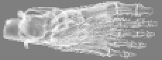
AnatomyPlot3D[{Entity["AnatomicalStructure", "LeftHand"]}, PlotTheme -> "Vintage"]Transparent appearance with emphasis on the bones similar to an x‐ray:
AnatomyPlot3D[{Entity["AnatomicalStructure", "LeftHand"]}, PlotTheme -> "XRay"]Highlight bones by combining the default bone color with the transparent theme:
AnatomyPlot3D[{AnatomyStyling[<|EntityClass["AnatomicalStructure", "Bones"] -> "Natural"|>], Entity["AnatomicalStructure", "LeftHand"]}, PlotTheme -> {"Transparent", Hue[.58]}]SphericalRegion (1)
By default, the rendered scene is centered at the center of the bounding box:
AnatomyPlot3D[Entity["AnatomicalStructure", "RightFoot"]]SphericalRegion can be used to recenter the scene around a specific scene element and constrain the view to the element's bounding sphere:
AnatomyPlot3D[Entity["AnatomicalStructure", "RightFoot"], SphericalRegion -> Entity["AnatomicalStructure", "RightThirdMetatarsalBone"]]Ticks (4)
Ticks are placed automatically in each plot:
AnatomyPlot3D[{Entity["AnatomicalStructure", "LeftHand"]}, PlotTheme -> "Classic", Axes -> True]Use TicksNone to not draw any tick marks:
AnatomyPlot3D[{Entity["AnatomicalStructure", "LeftHand"]}, PlotTheme -> "Classic", Axes -> True, Ticks -> None]Place tick marks at specific positions:
AnatomyPlot3D[{Entity["AnatomicalStructure", "LeftHand"]}, PlotTheme -> "Classic", Axes -> True, Ticks -> {{220, 250, 300}, {-100, -120, -150}, {650, 700, 800}}]Draw tick marks at the specified positions with the specified labels:
AnatomyPlot3D[{Entity["AnatomicalStructure", "LeftHand"]}, PlotTheme -> "Classic", Axes -> True, Ticks -> {{{220, a}, {250, b}, {300, c}}, {{-100, d}, {-120, e}, {-150, f}}, {{650, g}, {700, h}, {800, i}}}]TicksStyle (4)
Specify overall ticks style, including the tick labels:
AnatomyPlot3D[{Entity["AnatomicalStructure", "LeftHand"]}, PlotTheme -> "Classic", Axes -> True, TicksStyle -> Directive[Bold, StandardRed]]Specify tick style for each of the axes:
AnatomyPlot3D[{Entity["AnatomicalStructure", "LeftHand"]}, PlotTheme -> "Classic", Axes -> True, TicksStyle -> {Directive[StandardPurple, Bold], Directive[Bold, StandardRed], Directive[Bold, StandardBlue]}]Specify tick marks with scaled lengths:
AnatomyPlot3D[{Entity["AnatomicalStructure", "LeftHand"]}, PlotTheme -> "Classic", Axes -> True, Ticks -> {{{220, a, .1}, {250, b, .1}, {300, c, .1}}, {{-100, d, .2}, {-120, e, .2}, {-150, f, .2}}, {{650, g, .15}, {700, h, .15}, {800, i, .15}}}]Customize each tick with position, length, labeling and styling:
AnatomyPlot3D[{Entity["AnatomicalStructure", "LeftHand"]}, PlotTheme -> "Classic", Axes -> True, Ticks -> {{{220, a, .1, Directive[StandardRed]}, {250, b, .1, Directive[StandardRed]}, {300, c, .1, Directive[StandardRed]}}, {{-100, d, .2, Directive[StandardBlue, Thick]}, {-120, e, .2, Directive[StandardBlue, Thick]}, {-150, f, .2, Directive[StandardBlue, Thick]}}, {{650, g, .15, Directive[StandardBlue]}, {700, h, .15, Directive[StandardBlue]}, {800, i, .15, Directive[StandardBlue]}}}]Applications (1)
A more automated approach to labeling subparts can be obtained by making use of region properties of the anatomical structures:
anatomyCallouts[entities_, callouts_List] := Module[{scene, pr, sc, sr, cr},
	pr = PlotRange /. AbsoluteOptions[scene = AnatomyPlot3D[{entities}], PlotRange];{sc, sr} = {Mean /@ pr, Norm[Subtract@@@pr] / 2};
	cr = Rule@@@AnatomyData[callouts, {"Name", "RegionCentroid"}];
Show[scene, Graphics3D[{AbsoluteThickness[2], StandardRed, Line[{#[[2]], sr Normalize[(#[[2]] - sc)] + sc}]& /@ cr, Black, Inset[Style[#[[1]], Bold, 16], 1.1sr Normalize[(#[[2]] - sc)] + sc, Background -> GrayLevel[.95]]& /@ cr}], ImageSize -> {500, 400}]]anatomyCallouts[{Entity["AnatomicalStructure", "Skull"]}, {Entity["AnatomicalStructure", "FrontalBone"], Entity["AnatomicalStructure", "OccipitalBone"], Entity["AnatomicalStructure", "RightTemporalBone"], Entity["AnatomicalStructure", "RightParietalBone"], Entity["AnatomicalStructure", "LeftParietalBone"], Entity["AnatomicalStructure", "LeftTemporalBone"]}]Properties & Relations (1)
The models used with AnatomyPlot3D are the same ones obtained from the "Graphics3D" property used in EntityValue:
model = Entity["AnatomicalStructure", "HipBone"]["Graphics3D"]The structure of the models includes an Annotation for each subpart that can be useful for labeling and other reference keeping:
Cases[model, _Annotation, ∞] /. Annotation[body_, ann_] :> Inactive[Annotation][Graphics3D[body], ann]Neat Examples (4)
Use Overlay to place anatomical structures over a skin silhouette:
Block[{opts = {PlotRange -> Entity["AnatomicalStructure", "Skin"], ViewAngle -> 14°, ViewCenter -> {.5, 0, .7}}}, Overlay[{AnatomyPlot3D[{AnatomyStyling[{Directive[Lighting -> {{"Ambient", White}}, GrayLevel[.3]]}], Entity["AnatomicalStructure", "Skin"]}, Background -> GrayLevel[.2], opts], AnatomyPlot3D[{Entity["AnatomicalStructure", "AlimentarySystem"]}, opts]}]]Control Opacity when locating subparts within a transparent structure:
AnatomyPlot3D[{AnatomyStyling[<|_ -> Opacity[.15], Entity["AnatomicalStructure", "TricuspidValve"] -> White|>], Entity["AnatomicalStructure", "Heart"]}, PlotTheme -> {"Transparent", StandardRed}]Apply Rotate to anatomical structures:
Manipulate[AnatomyPlot3D[{Entity["AnatomicalStructure", "Neurocranium"], Entity["AnatomicalStructure", "ZygomaticBone"], Entity["AnatomicalStructure", "SphenoidBone"], Entity["AnatomicalStructure", "NasalBone"], Entity["AnatomicalStructure", "Maxilla"], Entity["AnatomicalStructure", "MaxillaryDentition"], Rotate[{Entity["AnatomicalStructure", "Mandible"], Entity["AnatomicalStructure", "MandibularDentition"]}, Dynamic[t Degree], {1, 0, 0}, {0.33, -106., 1470.}]}, SphericalRegion -> True, PlotRange -> Entity["AnatomicalStructure", "Skull"], PlotRangePadding -> 20], {t, 0, 20}, SynchronousUpdating -> False]
| |

| |
Apply ClipPlanes to specific objects in the scene:
Manipulate[
	AnatomyPlot3D[{Entity["AnatomicalStructure", "LeftUpperLimb"], ClipPlanes -> Dynamic[{InfinitePlane[{{0, -300, z}, {300, -300, z + 200}, {200, 0, z}}]}], Entity["AnatomicalStructure", "SkinOfLeftUpperLimb"]}],
	{z, 400, 1400}, SynchronousUpdating -> False
]Text
Wolfram Research (2016), AnatomyPlot3D, Wolfram Language function, https://reference.wolfram.com/language/ref/AnatomyPlot3D.html (updated 2019).
CMS
Wolfram Language. 2016. "AnatomyPlot3D." Wolfram Language & System Documentation Center. Wolfram Research. Last Modified 2019. https://reference.wolfram.com/language/ref/AnatomyPlot3D.html.
APA
Wolfram Language. (2016). AnatomyPlot3D. Wolfram Language & System Documentation Center. Retrieved from https://reference.wolfram.com/language/ref/AnatomyPlot3D.html